Digital Construction Platform
From Fall 2017 to Spring 2018 I worked on the MIT Media Lab’s Digital Construction Platform (DCP), a platform for large-scale on-site fabrication.
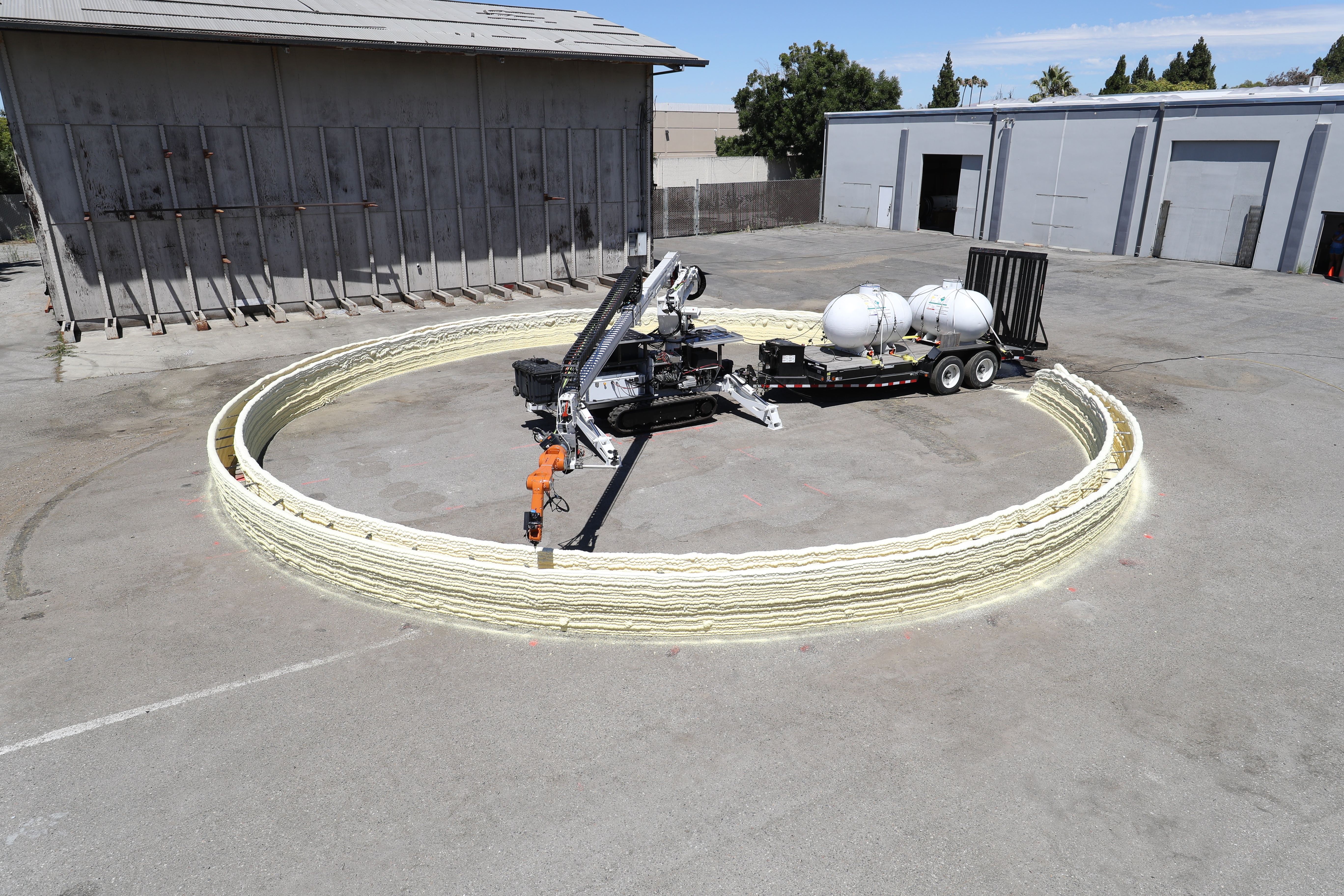
My responsibilities included prototyping a scanning LIDAR sensor package to extract environmental topography data that informed the design of the structure geometry and enabled construction on non-planar surfaces. To deliver the prototype, I employed the following skills:
- Mechanical design in SolidWorks and rapid prototyping via 3D printing.
- Electromechanical design of a self-contained sensor unit consisting of a LIDAR rangefinder, pan-and-tilt servo assembly, Arduino Mega, Raspberry Pi, and 5V power bank.
- Programming the Arduino to interface with and control the LIDAR sensor and servo motors (including resolving 1D rangefinder measurements to points in 3D space using servo motor encoder readings and the kinematics of the assembly).
- Bidirectional communication between the Arduino and Raspberry Pi to remotely operate the system and save the topography data.
The LIDAR Sensor
The LIDAR sensor is a Garmin LIDAR-Lite V3 rangefinder mounted on a 3D printed pan-and-tilt servo assembly. The LIDAR sensor and servo motors are controlled by an Arduino Mega, and data is output via a serial connection to a Raspberry Pi 3 Single Board Computer.
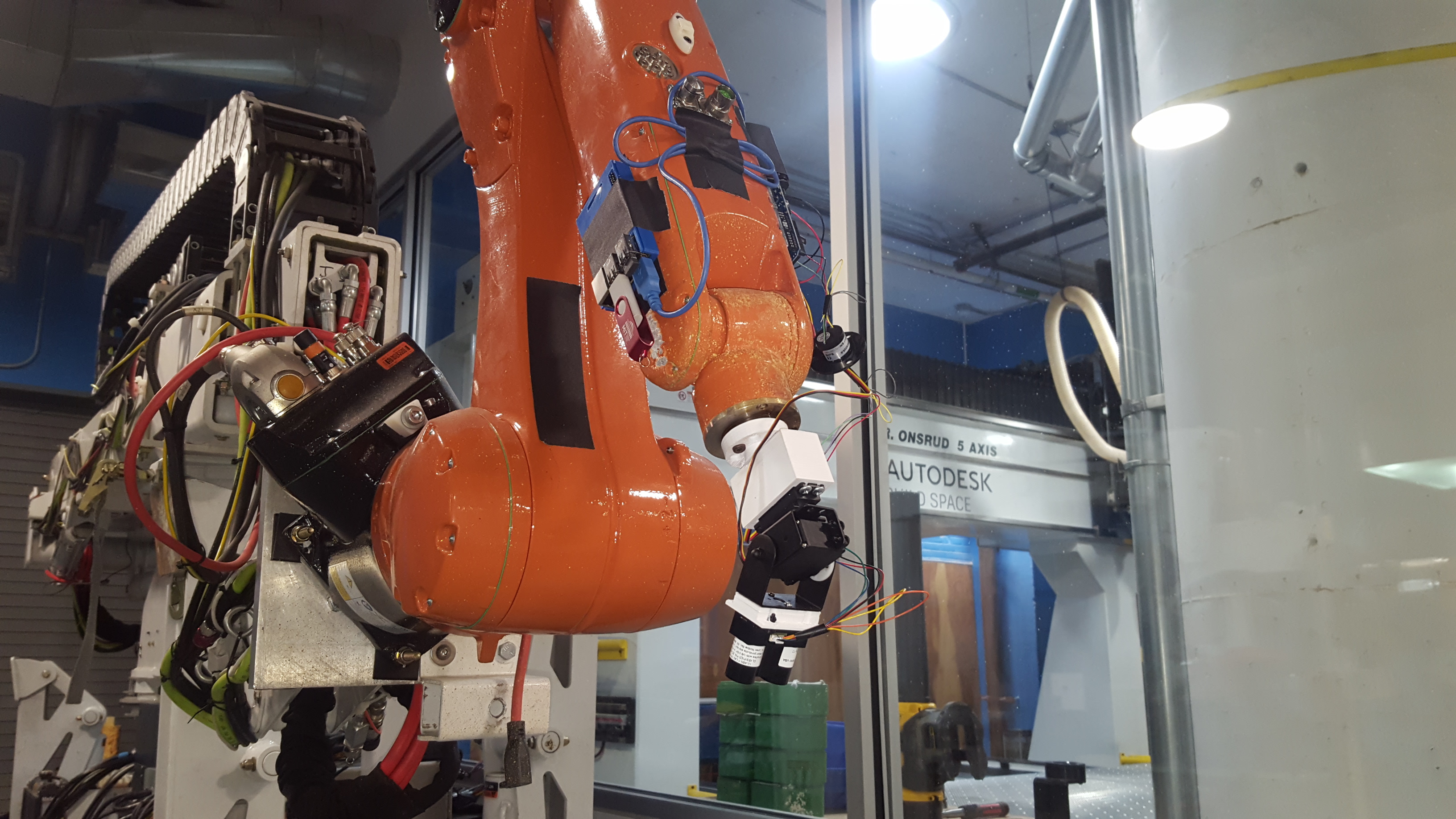
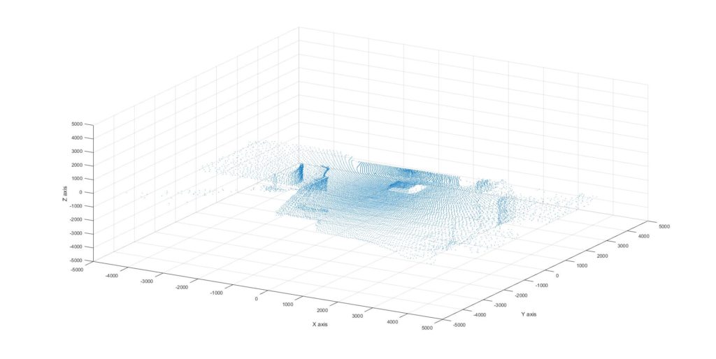
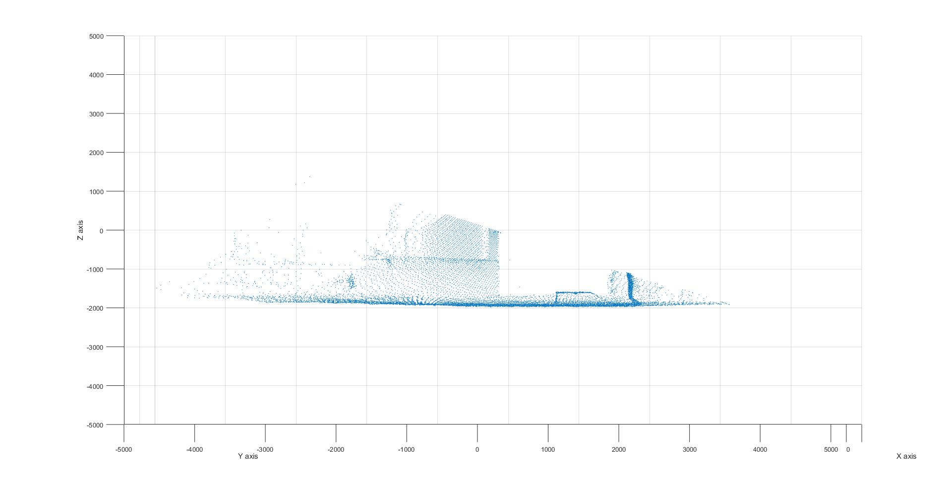
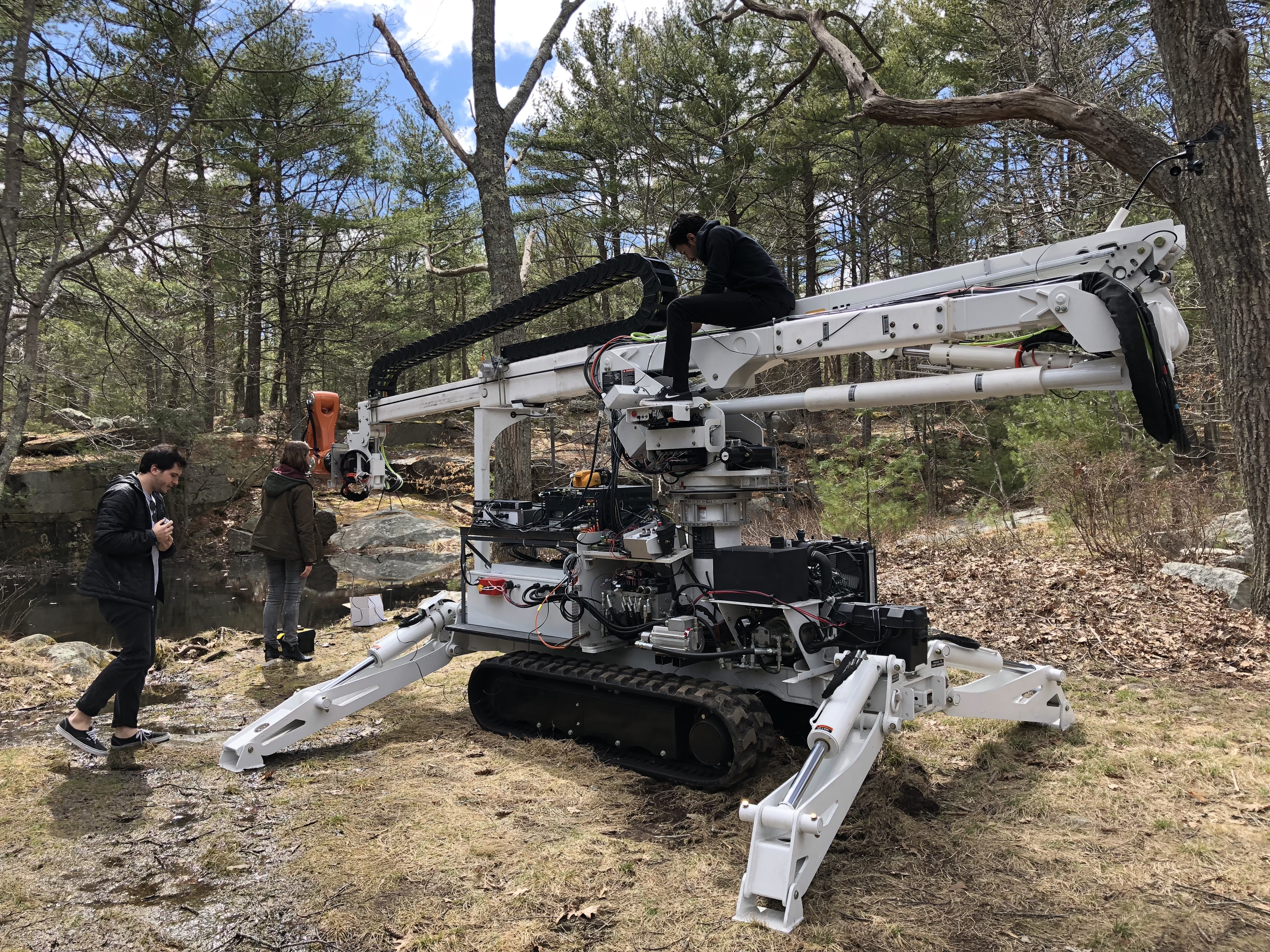
The LIDAR sensor only collects 1D range information in the direction of the laser emitter, so the sensor performs a hemispherical scan to collect 3D point cloud data. The encoder data from the servo motors is used to resolve each 1D range measurement produced by the LIDAR sensor to a point in 3D space. Below are a photo of the sensor performing a scan and the resulting point cloud plotted and viewed from multiple angles.
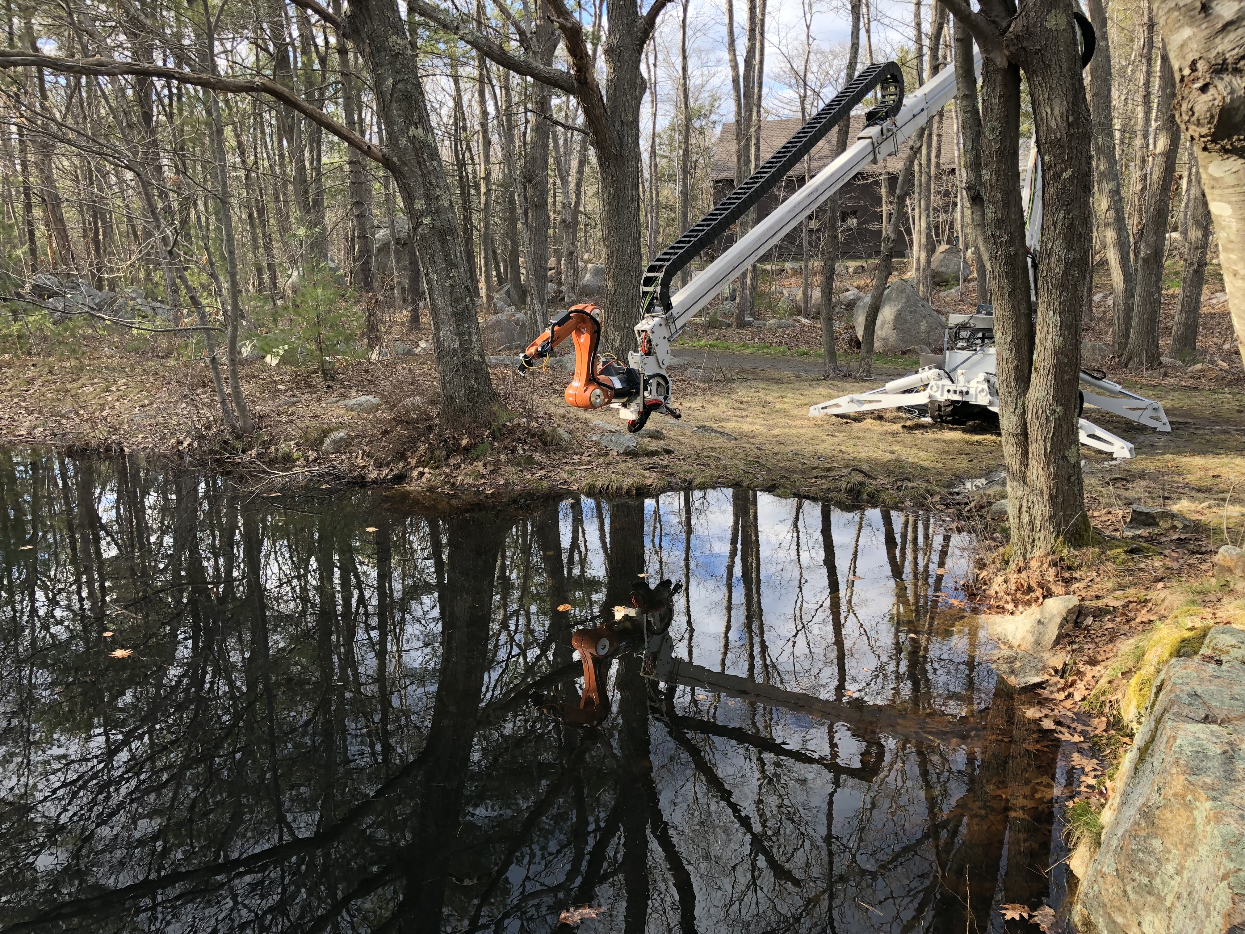
Field Testing
In order to test the LIDAR sensor along with the wind + temperature + humidity sensor, the team went to Ravenswood Nature Reserve in Western Gloucester, MA.
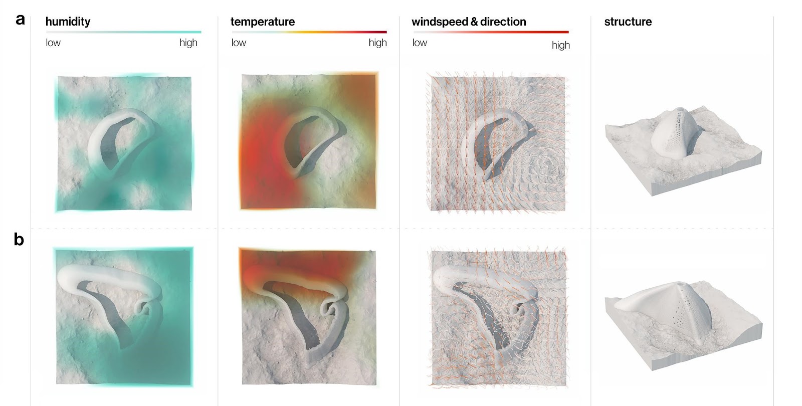
Together, the LIDAR, wind, temperature and humidity sensors informed the design of a structure specific to the test environment:
- LIDAR 3D point cloud data enabled the design of a structure geometry specific to the environment’s non-planar surface.
- Wind speed and direction influenced the location, arrangement, and porosity of the built structure. Wind data may also be used in the context of additive manufacturing to control the micro-macro manipulator in the presence of a wind disturbance force.
- Temperature & humidity influenced the structure’s wall thickness and porosity.
For more information, see the paper below.